0.72° basic step angle
Stepper Motor and Driver Packages with AC Power Supply
High torque at low speed
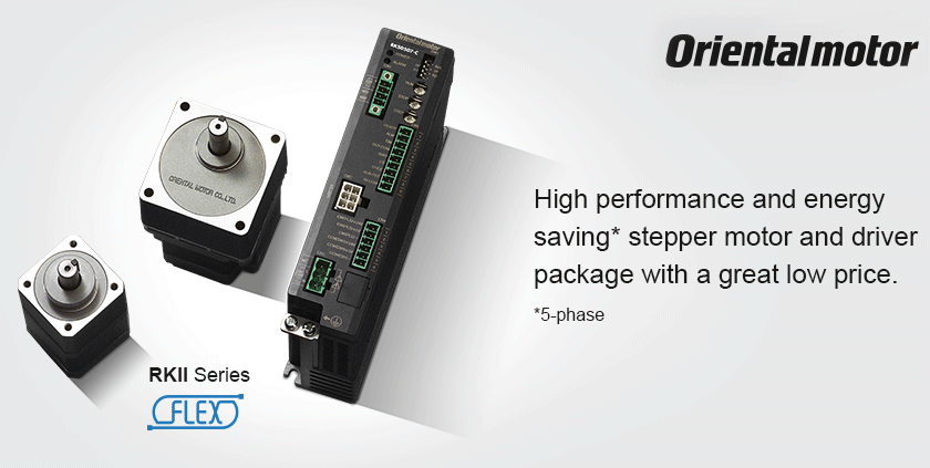
It is a 0.72° stepper motor and driver package with improved basic performance and ease of use, achieved by combining the newly developed high efficiency 5-phase stepper motor with a full digital control microstep driver to maximize motor performance.
SAVE Energy and Money
Benefit from compact size, and minimize your costs.
While achieving a significant improvement in motor performance, driver operations and functions, compared to conventional
products, the RKII Series has a new, low price.
RK Series Pulse Input Type,
60 mm frame size, round shaft
RKII Series Pulse Input Type,
60 mm frame size, round shaft
Space saving factor - less space and costs for cabinet
This new driver has been created by re-arranging the internal components, optimizing the usage of the size within the
driver. In addition, drivers can be installed side by side, reducing a significant amount of space.
When drivers are installed in contact with each other, the allowable ambient temperature range is 0 to 40°C.
RK Series Driver
Installation Area approx 94 cm2
RKII Series Driver
Installation Area approx 64 cm2
Multiple units can be installed in coherently with each other.
Conventional Model: RK Series Driver
RKII Series Driver
With the maximized motor performance, it is easy to achieve high efficiency and cost savings.
By optimizing the motor material, 47% of the power consumption has been reduced. This results in the decrease of electricity and CO2 emission. In addition, with lower heat generated by the motor, there is no need of using fans or radiation plates.
Power Consumption Comparison
Operating Conditions:
· Spin speed: 1000 r/min
· Load torque: 0.47 N.m
· Operating time: 24 hours a day
(Operation 70%, Stand-by 25%, Stop 5%)
365 days/year
| Items |
Conventional Model |
RKS566AC ◊ |
Comparison |
Reduced by |
| Power consumption during operation [W] |
204 |
106 |
98 |
48% |
| Power consumption during stand-by [W] |
14 |
13 |
1 |
7% |
| Power consumption [kWh/year] |
1281 |
678 |
603 |
47% |
CO2 emission equivalent
to power consumtion [kg/year] |
533 |
282 |
251 |
47% |
Lower Heat Generation - Less effort for temperature control.
By utilizing high-efficient technology, continuous operation is achieved due to the reduction of motor heat.
Reduced temperature
Heat distribution, shown in thermal image.
EASY Connection and Wiring
The redesigned driver is more compact and allows an installation close to other drivers and the wiring effort has been simplified.
The new I/O connector does not require a screw, eliminating the need for soldering or a special crimping tool. The motor connector can be connected easily by using a dedicated cable. This will reduce wiring time, maintenance and prevent mis-wiring.
Motor Connector Wiring
• No screw tightening

• Wiring time reduction
• Reduce problems caused by mis-wiring
I/O Connector Wiring
• No soldering
• No crimping tools
• Wiring time reduction
• Less maintenance
Selection
Free Motor Selection Service for Customers: Send us a motor selection inquiry via our website, fax or e-mail.
Motor Selector
Driver - connects to a wide variety of host systems.
Select the control method in accordance with your system requirements and your desired control method.
Pulse Input Type
Built-In Controller Type

Pulse Input Type
The motor can be controlled using a pulse generator provided by the customer. Operating data registered in the pulse generator is selected from the PLC to operate the motor.
Built-In Controller Type
How to Connect (for more information please click here)
Set the operating data to driver, the user could choose and command operation from host.
To connect with host, choose from
① I/O
② Modbus (RTU)/RS-485
③ Industrial Network.
In case, the user choose to connect via Modbus (RTU)/RS-485 or Industrial Network, the operating data can bedynamically parameterized if needed.

The function of a built-in pulse generator lets you build an operation system by connecting directly to a PLC. Since no separate pulse generator is required, the drivers of this type save space and simplify systems.

Through RS-485 communication, you can set operating data and parameters and input operation commands. A maximum of 31 drivers can be connected to one serial unit. There is also a function for simultaneously starting multiple axes. The unit also has a feature for starting multiple axes simultaneously. The unit supports the Modbus (RTU) protocol, which makes it easy to connect a PLC or similar device to the driver.

By using a Network Converter (sold separately), you can use EtherCAT communication, CC-Link communication and MECHATROLINK communication. Over these links, operating data and parameters can be set, and operation commands can be sent to the driver.
Built-In Controller (Stored Data) Type The burden on the programmable PLC is reduced because the information necessary
for motor operations is built into the driver. This simplifies the system configuration for multi-axis control. Set with control module (sold separately), data setting software or RS-485 communication.
Basic System Configurations
Operation Data Settings Parameter Changes
- Setting via RS-485 communication is possible.
- Data setting software can be downloaded from our website and USB cable CC05IFUSB can purchased separately
High Accuracy - High accuracy in positioning ±0.05°.
Positioning accuracy of the RKII Series is ±0.05° (± 3 arcmin). When the RKII Series is used with a ball screw as shown in the below drawing, the stopping accuracy becomes ±1.4 μm. The accuracy of the normal ground ball screw is ±10 μm, thus the accuracy is high enough for positioning operation.
High Torque - Improve cycle time of machinery.
The RKII Series is compact and produces high torque. The torque of the 42 mm frame size model has increased 50%. This contributes to a reduction in positioning and move time. The series includes 60 mm and 85 mm framesize models to cover a wide torque range.
Torque Comparison (42 mm frame size)
High Efficiency - Shorten time for positioning.
With conventional stepping motors, in applications where heat generation had to be suppressed, the operating current had
to be reduced, which also reduced torque. With the RKII Series, thanks to its low heat generating, highly efficient motors, the motor torque can be used fully to reduce positioning time.
Torque Comparison by Operating Current
In case of RKS566AC
Comparison of Cycle Time
(between deferent current of electricity)
In case of RKS566AC
Operating Conditions
- Moment of load inertia: 4x10⁻⁴ kgm2
- Load torque: 0.2 Nm
- Traveling Amount: 180°
Vibration has been reduced drastically.
Utilizing a full-time microstepping driver controlled by a digital system improves the vibration characteristics of the 0.72° stepper motor. Current control is also done by a high specification digital CPU. This model uses PWM control instead of
PAM control resulting in a sinusoidal wave form in each phase, significantly reducing vibration.
Current Waveform in Motor (theoretical figure)

Current in the motor is changed from trapezoidal wave to sinusoidal wave, which resulted in less vibration.
Vibration characteristics

Optimal resolution can be selected.
For pulse input type, 32 step angles can be selected. To easily upgrade from a 1.8° stepper motor, use the step angle setting
switch to match the existing input pulses to the desired output speed and position. There is no software or control module required.
For built-in controller type, the value can be between
200 p/r - 200,000 p/r.
Setting can be done by a Control
module, software or RS-485 communication.
Protective Function - Check troubles with protection function.
Many types of protection functions are integrated into the driver. A blinking LED (blink count determines alarm type) indicates when an alarm is triggered.
Example of alarm
- Main circuit overheating
- Overvoltage
- Command pulse error
- Overcurrent
- Undervoltage
- Electrolytic capacitor error
- EEPROM error
- CPU error
- Automatic electromagnetic brake control error
Example:
Alarm LED blinking three times
Overvoltage alarm
[Causes]
Power supply voltage exceeded
the permissible value.
A large inertial load was stopped
suddenly or lifted or lowered.