Easy to Use
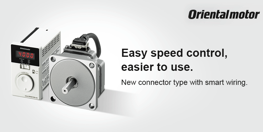
The new connector type in the compact, high-efficiency BMU Series, directly connects the motor and driver together. Smart wiring and water resistance performance (degree of protection IP66) have been achieved.

NexBL is the new brushless motor from China Motor. The entire motor structure has been redesigned in an effort to maximize the required performance. Unprecedented compact size, high power, and high efficiency.
EASY Configuration
Easy Operation
Turn & Press
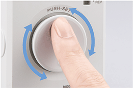
Turn the dial and set to the desired speed. The speed can be set just by pressing the dial.
Start/Stop
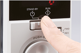
Can be easily driven and stopped with the operating switch on the front. There is no need to provide a switch externally.
Switching the Rotation Direction
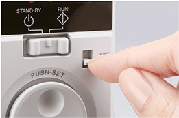
The motor's rotation direction can be switched with the rotation direction switch. It can even be changed during operation.
Easy Wiring
Direct Connection to the Motor
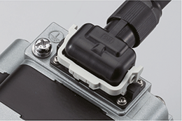
Easy connection between the motor and connection cable by inserting the connector and lowering the lock lever. Newly designed for small motors.
Easy Connection on the Driver Side too
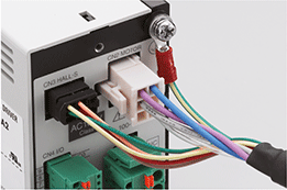
The driver connector is a small format connector that easily passes through flexible conduits and cable glands.
The Power and I/O Connectors Feature a Screwless Connector
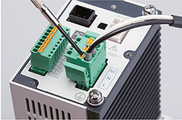
Connection to the power connector and I/O connector do not require any special crimp tools or soldering. Just insert the lead wire.
Easy Assembly
The Combination Type has a New Gearhead

The gearhead has improved gearmotor coupling accuracy due to the use of boss and installation surface cutting. It also produces less noise than conventional products. The combination type comes with the motor and gearhead already assembled, making assembly in the equipment easy.
Connector Type Features
A connector has been newly developed for small motors. Direct connection between the motor and driver is now possible.
Together with the improved motor structure, watertight and dust-resistant performance has also been increased, achieving a motor protection level of IP66.
New Connector
The gasket and O-ring are built-in, improving water ingress protection. A lock lever system which does not require screw fitting is employed, making connection easy.
Connector Structure
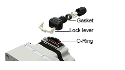
Installation Method

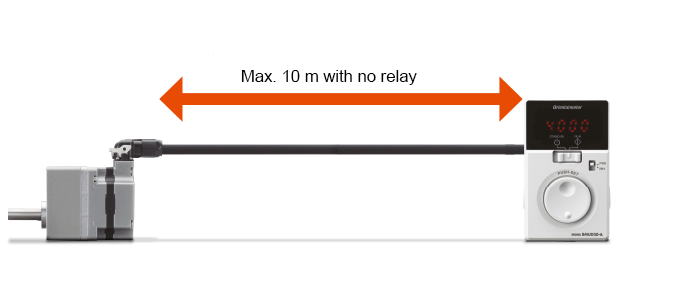
Directly Connect the Motor and Driver
Can be connected up to 10 m max. with no relay. Cable relay processing is unnecessary. The power line, signal line,
and ground wire are all contained in one cable, reducing wiring work.
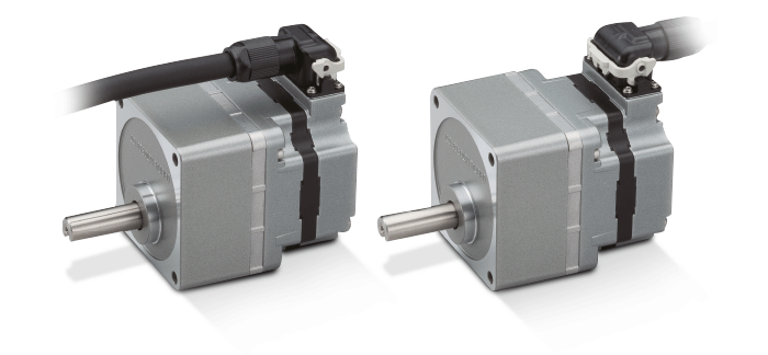
Select the Cable Pull-out Direction
Two cable pull-out direction options are available on geared type to suit the equipment.
Pull-out on output shaft side Pull-out on rear of the motor
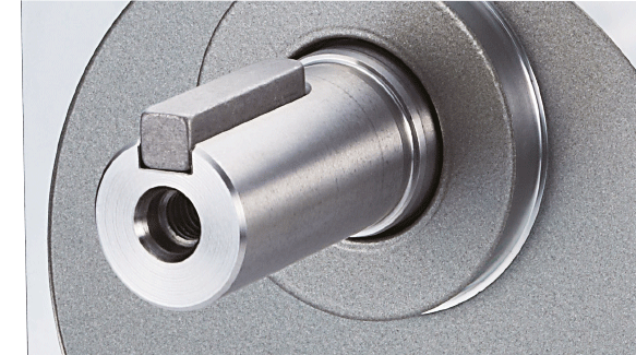
Stainless Steel Shaft in standard configuration
EURONORM X 10 CrNiS 18 9, which has excellent anti-rust and anticorrosion properties, is used for the shaft. Stainless steel is also used for the
parallel key and installation screws.
WIDE Speed control range
Brushless motors don't have brushes, which are the weak point of DC motors, so they create little noise and are maintenance-free. Since they use a permanent magnet, they are compact, high-power, and high-efficiency.
Broad Speed Control Range
Brushless motors have a broader range of speed control than AC speed control motors and inverters. They are suitable for applications that require constant torque from low speed to high speed.
Example:
| Product Group |
Speed Control Range |
Speed Ratio |
Brushless Motors
BMU Series |
80∼4000 r/min |
1:50 |
Inverter-Controlled
Three-Phase Induction Motor |
200∼2400 r/min |
1:12 |
AC Speed Control
Motors |
50 Hz : 90∼1400 r/min
60 Hz : 90∼1600 r/min |
1:15
1:17 |
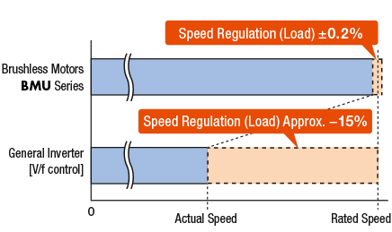
Stable Speed Control is Possible
Brushless motors constantly monitor feedback signals from the motor, compared with the setting speed, and adjust the applied voltage. This means that the motor rotates at a stable speed from low speed to high speed, even if the load changes.
Comparison of Speed Variation at 80% Load Factor (Reference value)
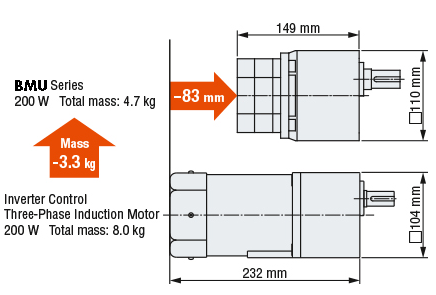
Slim, Light, High Power
Brushless motors contain a permanent magnet in the rotor, so they are slim, lightweight, and provide high-power. This contributes to equipment downsizing.
Showing the space saving potential
Contributes to Equipment Energy Savings
Brushless motors contain a permanent magnet in the rotor, inhibiting secondary rotor loss and greatly reducing power consumption. This helps the equipment to save energy.
Energy Saving potential illustrated
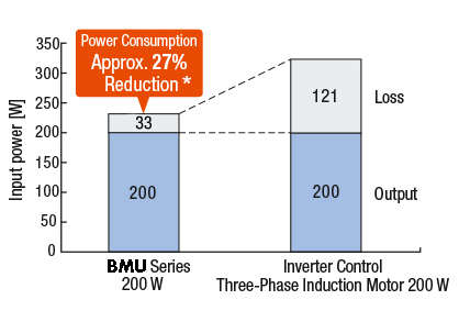
✽at net frequency 50 Hz
ENHANCED Control Possibilities
Speed Indicator
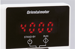
Displays the motor speed in 1 r/min resolution. By calculating the conveyor gear ratio and setting gear ratio parameters, the conveyor transportation speed can be displayed in m/s. The conveyor transportation speed can be confirmed directly.
Load Factor Indicator
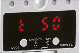
With the rated torque of the motor at 100% as a reference value, the load factor can be expressed as a percentage (40∼200%). The load condition during start-up, as well as the load condition due to the age deterioration of the equipment, can be confirmed. The figure shows a load factor of 50%.
Protective Functions
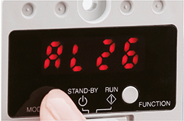
Provides various protective functions, such as an overload- and overvoltage protection function. When a protective function
activates, the alarm code is displayed on the indicator and an alarm signal is displayed.This simplifies troubleshooting.
4-Speed Operation
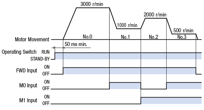
4-speed operation is possible by setting the data to operating data slots No.0, No.1, No.2 or No.3, and switching the digital inputs of the M0 and M1 terminals.
Set the Acceleration/Deceleration Time
Acceleration time and deceleration time settings can be adjusted with the acceleration/deceleration time potentiometer, as well as digitally set.
Setting Range:
0.0∼15.0 sec (initial value: 0.5 sec)
In the case for digital setting, acceleration and deceleration time can be independently set, so times can be freely set by fine-tuning shock alleviation when the load has started and stopped, together with cycle time.
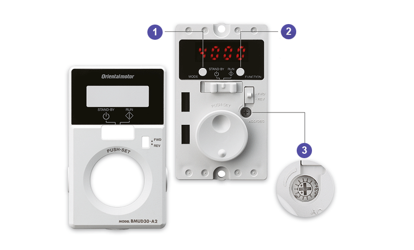
Various functions can be set by opening the front panel of the driver.
MODE Key Changes the operating mode.
FUNCTION Key Changes the indication and functions for the
operating mode.
Acceleration/Deceleration Time Potentiometer
These functions that can be set while the front panel is opened
- Motor start/stop
- Adjusting the operating speed
- Setting the operating speed
- Switching the rotation direction
- Changing the indication
- Indicating the operating speed when the speed reduction/speed increasing ratio is set
- Setting the acceleration/deceleration time
- Dial operation lock
- Speed setting for the 4-speed operation
- Speed limits setting
- Validating the external operating signals
- External input/output signal allocation
- Setting the overload alarm detection time Except when shaft is locked
- Load holding function for output shaft
Basic functions are available even when the front cover is attached
